Top ventilation for top chefs
FX-SwingControl

FX-SC control and monitoring unit

FX-SC is intended to connect Turbo- and UV-Turbo-hoods to building’s automation system.

FX-SC-unit controls the operation of the Turbo-motor (on/off) with the building automation time program via the BACnet IP or
Modbus TCP  interface.
FX-SC is delivered as pre-programmed.
Identified information about grease filters ( Turbo/UV-Turbo), motors rotation speed, hood chart and recommended maintenance interval are pre-programmed at every FX-SC.


Functioning principle


FX-SC alkunäyttö UV

FX-SC-unit controls the operation of the Turbo-motor (on/off) with the building automation time program
via the BACnet IP or Modbus TCP  interface.

The FX-SC unit allows to control and follow all Turbo- and UV-Turbo grease filters connected to FX-SC:
set a maintenance alarm, select motors rotation speed and follow UV-lamps operating time.


FX-SC alkunäyttö

FX-SC gives an alarm to building automation or all factors affecting Turbo- /UV-Turbo- grease filters operation, such as power failure, need for maintenance, end of UV-lamps effective operation time and motors rotation speed is less than 200 rpm Alarm and status information is displayed on screen and simultaneously transmitted to building automation system via chosen interface.


FX-SC is delivered as pre-programmed. Identified information about grease filters (Turbo/UV-Turbo), motors rotation speed, hood chart and recommended maintenance time are pre-programmed to every FX-SC.
One FX-SC unit can be connected to 1-12 Turbo/UV-Turbo grease filters.


Product structure

FX-SC-powered by Fidelix


FX-SwingControl


Clear 10,1″ touchscreen.
Building automation connection
RJ45 BACnet IP / Modbus TCP

(inside the cover).
Connection to building automation
system via local area network,
WAN-port.


FX-pohja -liittimet


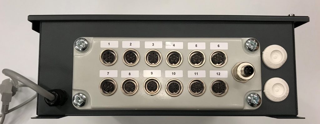
6-pin connector, 12 pcs + control current cable (0-10 V)
One FX-SC unit can be connected to a maximum of 12 Turbo or UV-Turbo.

Relay-outpot, Potential-free normally open contact.
The maximum load is 6A/230VAC or 5A/30VD

Power cord, socket plug (230V, 10A).
Length 2 meters

Note! The power cord serves as the disconnect device for the center’s power supply and should be connected to a grounded electrical outlet located near the device and easily accessible to the user.


Relay-alarms external connections connector,
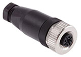
4-pin female connector Binder series 713, type 99 0430 14 04, (supplied separately).
Wires 1-2 are connected to the connector. (2-wire connecting cable from the building automation).

Relay alarm is general alarm.


Installation:
FX-SC must be installed to a place, where it can be easily used and is not exposed to
splash water.
FX-SC delivery includes:
– FX-SC-unit as pre programmed
– connection connector
– manual

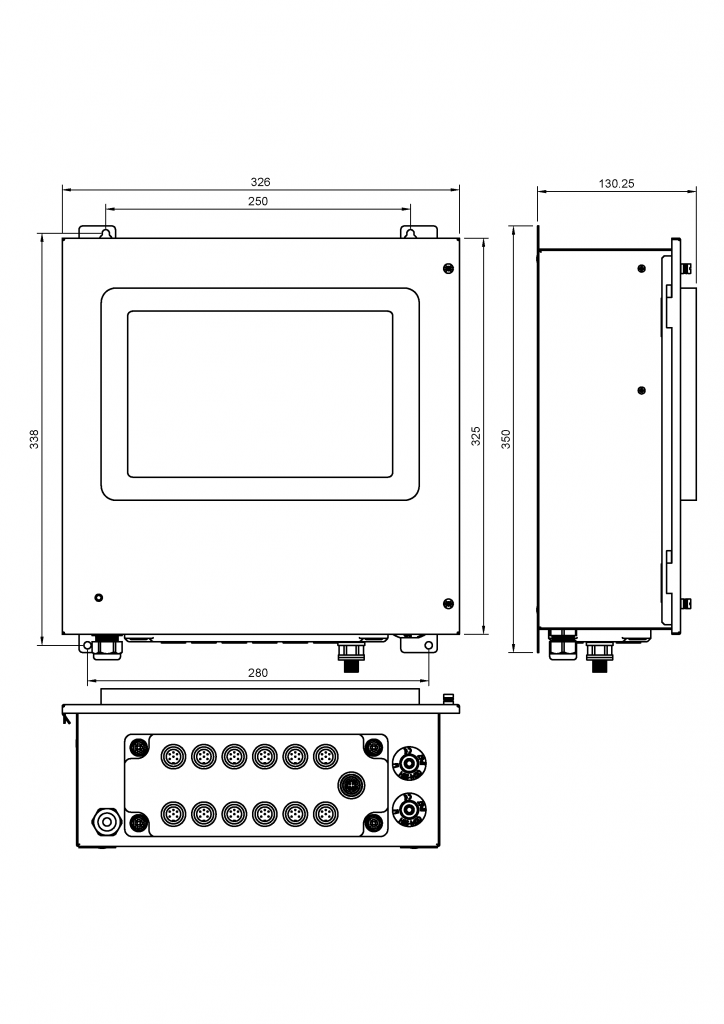
Dimensions


Dimensions:

326 x 325 x 130 mm

Operating voltage:

220-230 VAC

Power consumption:

max. 200 W

Operating temperature:

0… +40°C

FX-mittatiedot


Designing


Ventilation designer

  • Selects and marks the location for FX-SC- unit.


Electrical designer

  • Selects the socket location for FX-SC
  • FX-SC is connected as a separate supply to the mains via socket connection.


Automation designer

  • Designs a connection to building automation, primarily with RJ45 (BACnet IP / Modbus TCP) CAT6-wire or with 2-wire relay-alarm wire. (NOMAK 2x2x0,5+0,5 -cable)
  • Designs points for alarms for both motor and UV light status information in the chosen communication protocol.
  • All alarm and status information is also displayed on the touchscreen with symbols.

FX-SC BACnet registry listing

FX-SC Modbus TCP registry listing

FX-SC EDE registry listing

Example

FX-SC Automation scheme

Operation control

  • Hoods operations are controlled (on/off) with the building automation time program via the BACnet IP or Modbus TCP -interface.
  • The operation authorization for Turbo- /UV-Turbo -grease filters is set by locking grease filters power supply to the operation of the exhaust fan by relay control.
    (Turbo- /UV-Turbo grease filter are not allowed to operate / get power, if the exhaust fan is not running)
  • During maintenance, set FX-SC -unit to OFF-status from the touchscreen.
    (This avoids unnecessary alarms caused by maintenance)
  • Note! Turbo- and UV-Turbo- grease filters receive power, even FX-SC- unit is at OFF-status. Turn off the grease filters power supply from the safety switch.
  • After the maintenance, connect the power supply ON from the  safety switch and change FX-SC-units status to ON.


Control cables are connected to each (UV-)Turbo, from which the are connected to the FX-SC-unit. 12 (UV-)Turbo can be connected to one FX-SC-unit.

The safety switch is mandatory and must be installed in the immediate vicinity of the hood.

(Safety switch , socket/ outlet box and dashed cables are not included in the Jeven delivery)

Product code

JSI-UV-Turbo -3000x2600x540 -6×250 -5×315 +750 l/s -850 l/s –FX-SC

Copyright 2025 © Jeven – ammattikeittiöiden ilmanvaihtoratkaisut | Privacy statement